SimTrack: Object Modeling
SimTrack uses textured meshes for pose tracking and provides a simple tool to supplement these meshes with SIFT keypoints for pose detection.
The geometry and appearance of richly textured objects can be obtained with relative ease using Autodesk 123D Catch (preferably the Windows application). Autodesk provides extensive tips for a successful shoot. In summary you’ll want to:
- disable the camera’s auto-exposure and flash
- place the object on a newspaper (as below) to facilitate camera pose estimation
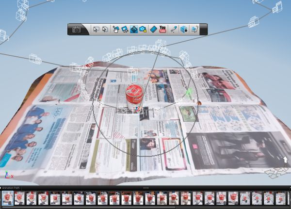
- take about 40 pictures in total, moving around the object in small steps in one high and one low loop (see the recovered camera positions below)
Upload the pictures through the Windows application and wait for them to be processed. If all goes well, it should return an initial model similar to this:
Click on the pictures one by one to ensure that they correctly map onto the reconstructed model. Either remove or manually stitch grossly misaligned images. Although typically not necessary, this step is critical to avoid blurry textures.
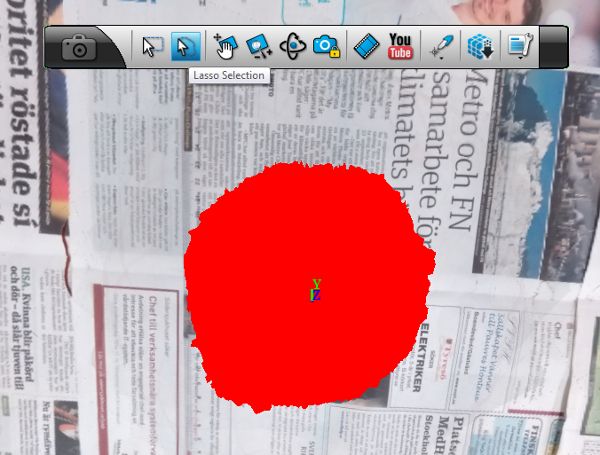
The initial model contains too much of the background. Use the Lasso Selection tool to select the object itself.
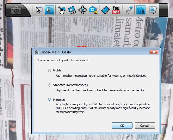
Re-process the mesh at maximum quality.
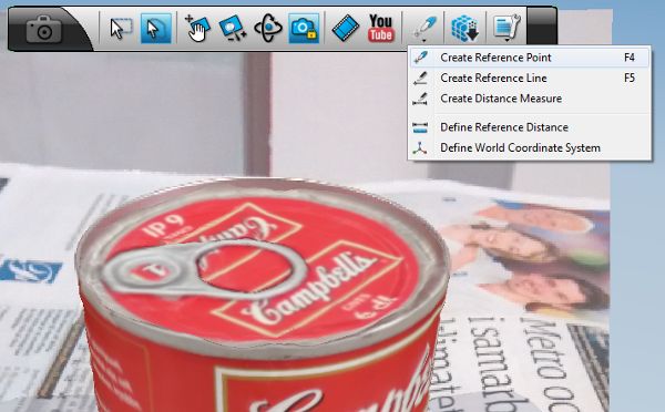
The next step consists of introducing an absolute distance measure to the scene. This requires identifying two reference points on the model for which the real-world distance can be established easily. Use F4 to create a new point.
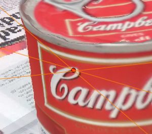
This point needs be marked in a number of pictures (e.g. 3) in order to triangulate its position on the model.
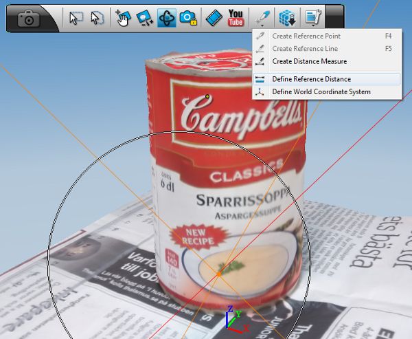
Repeat this procedure for a second reference point and select Define Reference Distance.
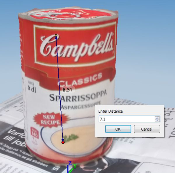
Connect both points and enter the absolute distance in centimeter. 123D Catch only allows one decimal so we’ll convert this to meter later on.
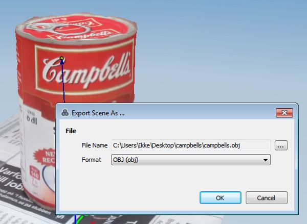
Export the scene as Wavefront OBJ-file. This concludes the 123D part.
Next, we’ll remove the supporting surface from the object. This is straightforward with Meshlab. Rotate the object as below, and select the bottom region using the Select Faces in a rectangular region tool.
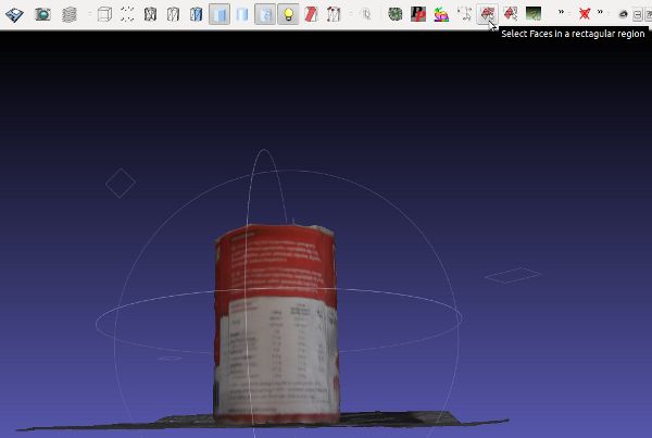
Press delete to remove the faces. Rotate and repeat until only the object remains.
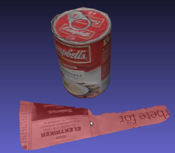
Export the mesh as Wavefront OBJ.
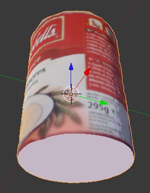
Next, we’ll use Blender to reposition the object. This step is not critical but it simplifies the interpretation of the estimated pose. For example, the object can be translated and rotated until the front view looks like this:
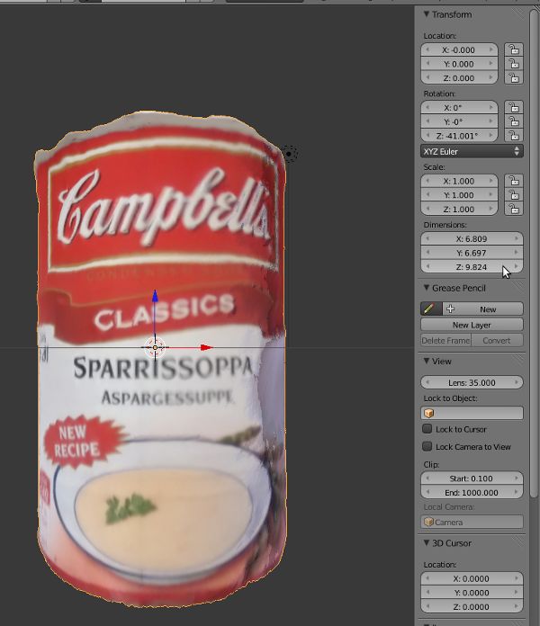
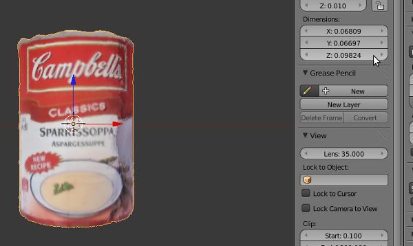
SimTrack and ROS use meter as unit of length so we’ll need to rescale the dimensions.
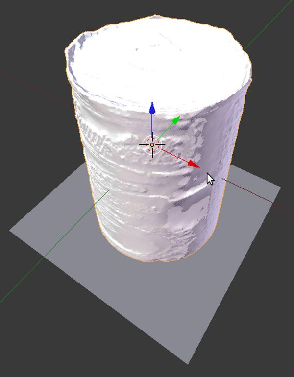
The object is now ready for use, but pose reliability evaluation can be improved by adding a surface to close the bottom of the (now bottomless) object. Add a plane and position it to intersect the bottom.
Add a boolean modifier to the object and intersect with the plane.
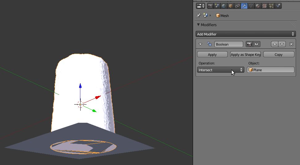
After removing the plane, the object has a bottom. The texture of this bottom will be somewhat random but this will help to signal the tracker that tracking has failed.
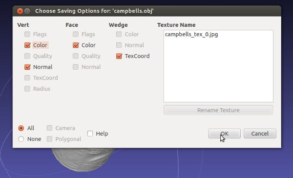
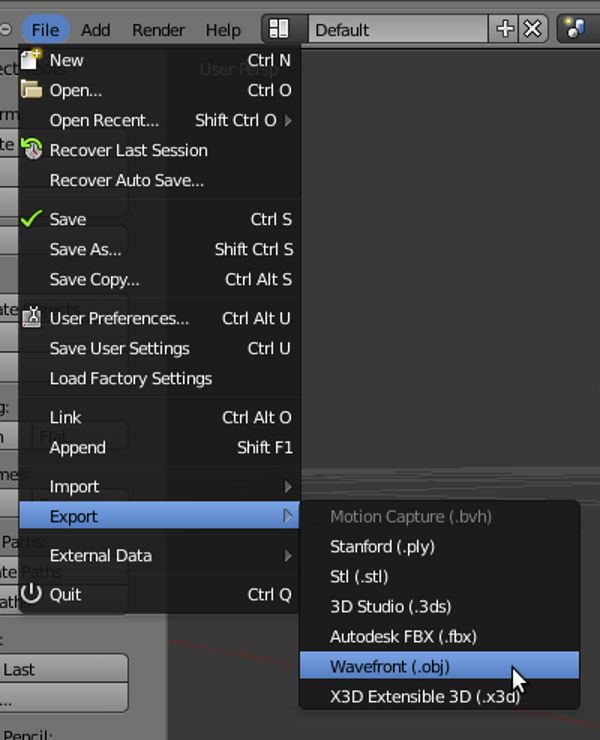
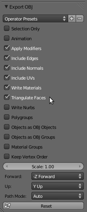
Export the model as Wavefront OBJ.
Make sure you Include Normals and Triangulate Faces!
Open the generated .mtl-file and remove the path from the map_Kd options.
map_Kd campbells_tex_0.jpg
Store all three files (.obj, .mtl, .jpg) in a folder with the same name as the .mtl and .obj files.
campbells/
   campbells.obj
   campbells.mtl
   campbells_tex_0.jpg
Perform a final check by opening the .obj-file in MeshLab and verify that the texture is visible.
Next, generate the SIFT-model using SimTrack:
rosrun interface cmd_line_generate_sift_model <path_to_obj_file>
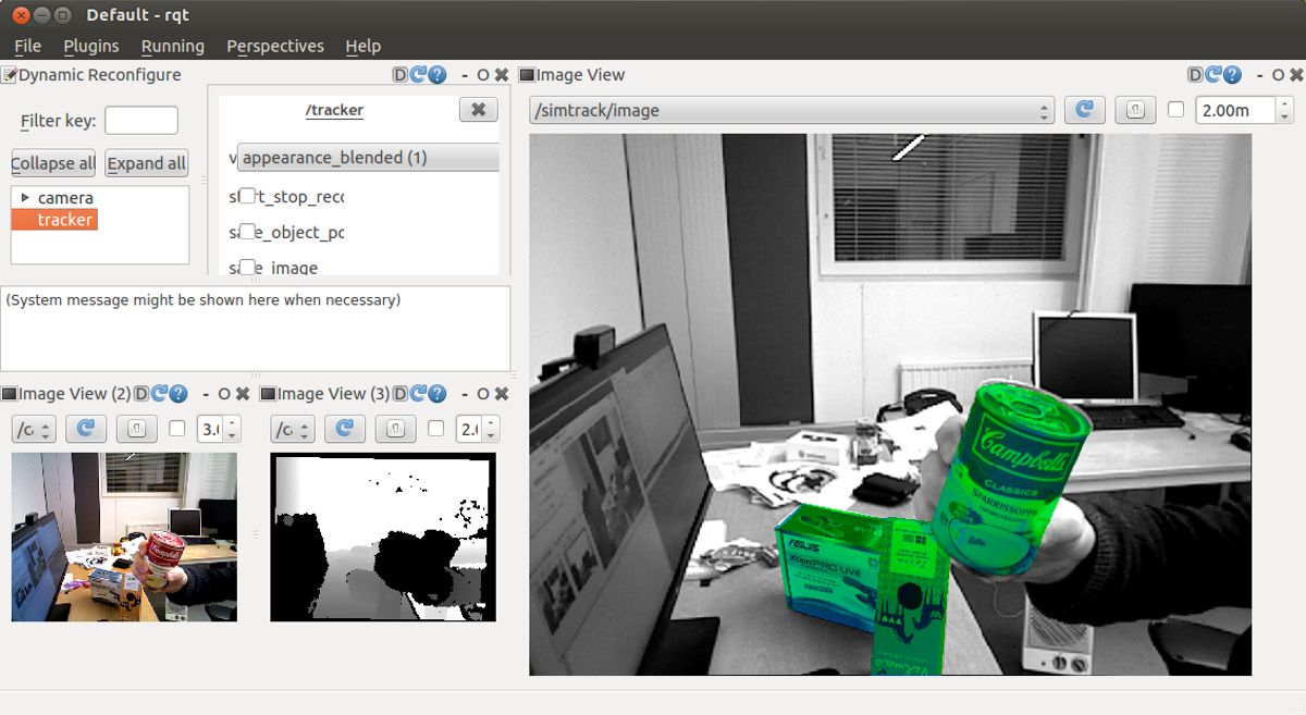
Your object is now ready for pose detection and tracking!